The iRP is involved in several R&D projects with international research
organizations and industrial partners.
The usage of MiRPA is not limited to the field of robotics. Every time a modular, scalable, and flexible real-time system is desired, MiRPA brings in its great advantages.
The Approach of Decision Trees
Decision trees are used as basis for the approach to realize on-line trajectory generation for N-dimensional space with arbitrary input values (Fig. 1) and synchronization between all degrees of fredom as shown in Fig. 2. The figure illustrates a simple case for third-order on-line trajectory generation with and without synchronization for three degrees of fredom. In correspondence to Fig. 1 a function, which maps the 8N-dimensional space onto 3N-dimensional space must be specified (with N = 6 for Cartesian space). Defining this function is the major part of this reasearch work. Once defined it would result in the classical trajectory progression with rectangular jerks as shown in Fig. 3, which depicts the most trivial case of a third-order trajectory.
System Overview
Fig. 2 describes the system, which has been developed in our institute. In the first step the assembly group is specified using symbolic spatial relations (Fig. 3). The user only has to click on the appropriate surfaces to do this. Possible contradictions and errors produced by the user can automatically be detected by the system.
After specification of assembly groups, assembly sequences are generated applying the assembly-by-disassembly strategy.
After determining the assembly sequence a collision free path planner has to be applied.
Furthermore, the assembly operations have to be transformed into appropriate skill primitive nets. A skill primitive net consists of skill primitives arranged in a graph, where the nodes represent the skill primitives and the edges are annotated by entrance conditions. Each skill primitive represents one sensor based robot motion.
With this concept, many different sensors can be used simultaneously. Currently we have employed cameras and force torque sensors.
Planning of such processes is carried out in virtual environment, hence displacements between real world and virtual world may occur. Theses displacements are treated by skill primitive nets successfully. Therewith a system for planning, evaluation, and execution of assembly tasks is provided.
The flexible and automated flow of materials, e.g. between different work cells and a computer controlled warehouse, becomes more and more important in modern factory environments. To obtain such a flexibility it is obvious to use autonomous guided vehicles (AGV). Many of the autonomous guided vehicle concepts, which are known from literature, use highly specialized on-board sensor systems to navigate in the environment. In contrast to these concepts, the flexible transport system MONAMOVE proposed by us uses only simple, low-cost on-carrier sensors in combination with a global monitoring system and a global navigation system. This combination of global monitoring and global navigation enables the carriers to navigate without any fixed predefined paths.
Even in simple situations, the selection of optimal robot paths depends on many factors (e.g. obstacle density, direction of motion, velocities). Mathematical models are thus a crucial foundation for statistical motion planning. To describe obstacle motions, two models -- differing in precision and complexity -- have been developed: Stochastic trajectories permit a precise evaluation of robot paths with respect to collision probability and expected driving time (which takes into account that the time to reach the goal also depends on the costs for non-deterministic evading maneuvers). The stochastic grid is a simpler representation, which is used in order to plan robot trajectories with minimum collision probability.
The paths generated by the statistical methods have been evaluated and compared to results obtained with a conventional planner, which minimizes the path length. Naturally, the statistically planned paths are longer as they purposely incorporate detours. In dynamic environments, however, the detours allow to significantly decrease collision probabilities and the expected driving time compared to the conventional trajectories.
Project Description
Within the scope of an cooperative research project with the Klinik und Poliklinik für Hals-Nasen-Ohrenheilkunde/Chirurgie of the "Rheinische Friedrich-Wilhelms-Universität Bonn" we are investigating methods that allow a robotic manipulator to guide an endoscope during an endonasal operation completely autonomously. The objective of the project is an intelligent guidance of the endoscope that fulfils the following requirements:
Project Goals
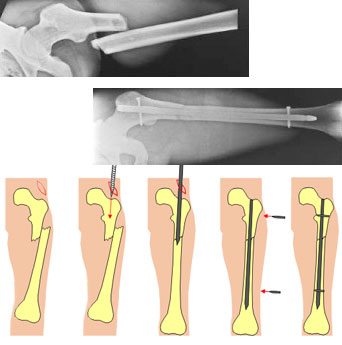
The primary goal of this research project is the development and evaluation of computer and robot assisted methods in order to support this challenging surgical procedure. With the combination of image analysis, force/torque guided robot control, and preoperative planning and simulation, the achievable reduction accuracies should be increased.
Pose Estimation of Cylindrical Objects for a Semi-Automated Fracture Reduction - Summary
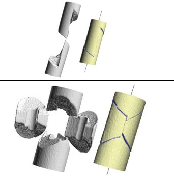
Below we present the results of our method for computing the relative target transformations between broken cylindrical objects in 3d space.
我们首先计算的位置和方向the axes of every cylindrical object. This is achieved by a specially adapted Hough transform. These axes are the most important attributes for the segmentation of fractured bones and can also be used as an initial pose estimation (constraining 4 of the overall 6 degrees of freedom of the reduction problem).
After these preprocessing steps, the relative transformation between corresponding fracture segments can be computed using well-known surface registration algorithms. Here we are using a special 2D depth image correlation and a variant of the ICP (Iterative Closest Point) algorithm. A project goal is using these methods for computing the target poses of bone fragments in order to allow for a computer assisted semi-automated fracture reduction by means of a robot.
Fracture Reduction using a Telemanipulator with Haptical Feedback - Summary
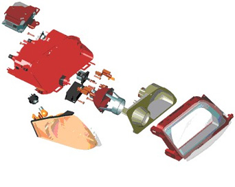
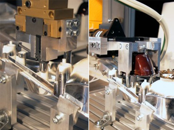
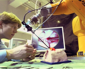
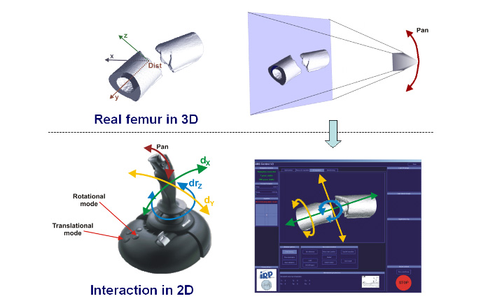
我们开发了一个复杂的系统,which allowed to use a robot as telemanipulator for supporting the fracture reduction process. Our robot is a standard industrial Säubli RX 90 robot. The robot is controlled by the surgeon by means of a Joystick with haptical feedback. Intraoperative 3D imaging of the fracture is the base information for the surgeon during reduction. These 3D volume images are automatically segmented by the PC resulting in highly detailed surface models of the fracture segments (cp. the figure below), which can be used by the surgeon to precisely move the fragments to the desired target poses. An optical navigation system ensures that the 3D scene presented on the PC display is always in accordance with the real surgical situation; the virtual 3D models always move in the same way as the real bone fragments, which are moved by the robot.
All forces and torques acting in the operation site can be measured by means of a force/torque sensor mounted at to robots hand. These forces are fed back to the joystick. This way, the surgeon is able to feel the forces acting on the patient because of distracted muscles or contacts between the fracture segments.
Results
In a first test series, the telemanipulator system was evaluated in our anatomy lab using broken human bones (without surrounding soft tissue). It could be shown that reduction accuracies with mean values of about 2° and 2mm can be achieved for simple fractures. Even for complex fractures the achievable accuracy stays below 4°. From a clinical point of view, these values are more than acceptable.
Furthermore, the telemanipulator system was also tested on human cadavers; complete specimens with intact soft tissues around the broken bone. The results have been similar to those outlined above. In addition we could show that to telemanipulated reductions achieve significantly higher reduction accuracies than manual reductions, which have been performed by an experienced surgeon on the same fractures.
Conclusion
The presented form of visualization and interaction with a telemanipulator system for fracture reduction in the femur turned out to be efficient and intuitive. All test persons have been able to perform reliable reductions with high reduction accuracies after only a short time of learning. These results clearly show the potential of robotized fracture reduction, which will ensure high quality outcomes of such operations in the future.
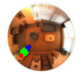
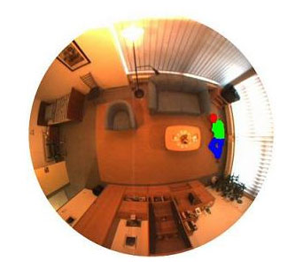
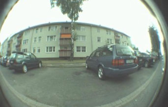
Using fish-eye cameras have the advantage of mapping the whole room onto just one image. A single pinhole-like or pan-tilt-zoom camera can only map a part of the room.
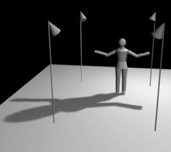
检测落在晚上我们整合活动approaches. Infra-red lights are mounted at different locations in the room, preferred at the ceiling. The shadow information is used to distinguish between a standing and a lying person. As can be seen in the following figures the shadow of a standing person is much bigger than the one of a lying person.
Till now we just consider fall detection, but of course fall prevention is another challenging task. Changes of the gait can be due to diseases and can result in a fall. Visual fall prevention allows the detection of these changes and e.g. the notification of the general practitioner.
This work has been supported by the Deutsche Telekom which is kindly acknowledged
Methods
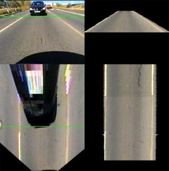
In many of our approaches for vehicle detection we use a top-down-view that is generated by projecting the camera pixels via Inverse Perspective Mapping (IPM) onto the street as can be seen in the image below and in the corresponding video. In this view we are looking down onto the street plane at right angle. Thus, no perspective mapping has to be considered for the distance calculation of two arbitrary points of the street plane, which simplifies processing of many algorithms.
One of our approaches uses this top-down-view to generate a street texture that describes the expected appearance of the street. In the figure below (a video is also available) you can see the generated street texture in the right column and the source images in the left column. The top row shows the view as seen from the camera and the bottom row shows the corresponding top-down-view. Source image and street reference texture are compared in order to detect approaching vehicles indicated in the figure below and in the video with a green line.
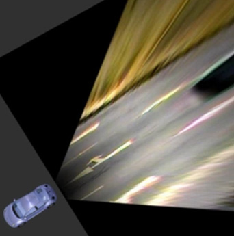
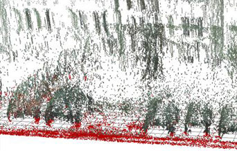
As we only have one camera at each side, we can not use stereo vision to gather 3D information. But because the car is moving, we can use structure from motion. This technique uses two views of a scene from different viewing angles to triangulate points in the 3D world and calculate their exact position. The result is a 3D scatter diagram of the passed area.
Results
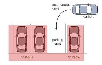
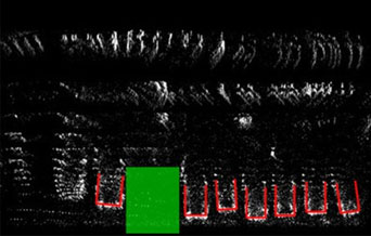
An example for such a scatter diagram can be seen below (image: 3D Scatter diagram). Every point in this diagram represents a real 3D point. Points at the street level are colored red, obstacles (= points above the street level) are displayed in black. If every 3D point is projected on its corresponding point in the ground plane, a top down view is created which shows the whole scene as seen from above. Now patterns become visible which can clearly be identified. Cars, for example, build a pattern shaped like the letter "U". If some of these can be found in the top down view, the positions of cars are clearly recognized. Free parking spots are now detected by searching for free space between these cars. For an illustration of the process, see the following image. Recognized cars are highlighted in red, free space is marked green (image: Topdown view of the scene). If a parking space is found, the automated parking process can be initiated.
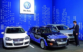
Experimental vehicle: Paul
The current experimental vehicle Paul (German: "Parkt allein und lenkt") uses our vision-based parking spot detection. Paul was presented at the Hannover fair 2008 and demonstrates Volkswagen's Park Assist Vision system.
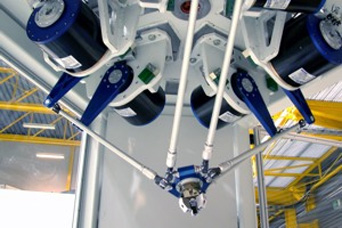
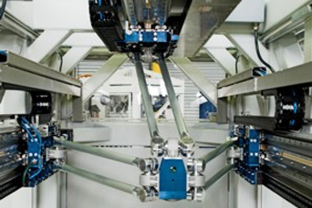
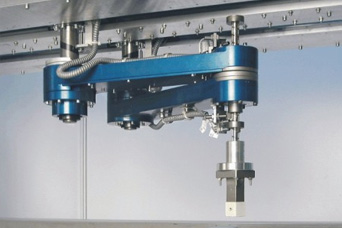
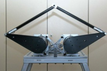
The aim of the Collaborative Research Center 562 is the evolution of methodical and component related fundamentals for the development of robotic systems based on closed kinematic chains in order to improve the promising potential of these robots, particularly with regard to high operating speeds, accelerations, and accuracy.
To reduce the sequence time for handling and assembly applications the most essential goal is to improve operating speeds and accelerations in the working space for given process accuracy. By using conventional serial robot systems these increasing requirements end in a vicious circle. Under these circumstances the request of new robotic systems based on parallel structures is of major importance.Owing to their framework construction by rod elements, which are poor in mass, parallel structures offer an ideal platform for an active vibration reduction. The integration of these adaptronic components with special adaptive control elements is a promising effective way to make robots both, more accurate and faster and consequently more productive.
The basic topics in the Collaborative Reserach Center 562 are:
participating "institutes":